Thank you for purchasing White Oak Audio Design’s TM-1001 Upgrade Power Supply and Amplifier Board. White Oak Audio Design products are meticulously engineered and tested to ensure a direct drop-in fit for your tuner.
The assembled and installed upgrade Power Supply Board will convert your TM-1001 tuner power system to a quieter but more robust and reliable power supply than the original one supplied in your tuner. Power supply board failure is quite a common cause for failure in the TM-1001 tuner.
Upgrade board features:
- Low noise rectification circuits utilizing high speed, high performance, and low noise Schottky barrier rectifiers replacing the original standard recovery silicon rectifiers. Schottky barrier rectifiers do not have the reverse recovery current noise effects of the original rectifiers used in the TM-1001.
- The original Auto-Magic circuitry that the TM-1001 made famous with upgrades to its function with higher quality components than the original.
- Improved AC line power factor due to soft rectification circuitry.
- Significant increases in the input and output capacitance on the positive and negative voltage rails.
- Symmetrical plus and minus 13V precision linear regulators to replace the original zener based voltage regulators. These regulators employ short circuit current protection as well as thermal protection and shutdown in the event of downstream circuit malfunction.
- Heat sink provision for both the positive and negative voltage regulators. Mechanical tie down provisioning for the large power regulators adds to the reliability of the power supply.
- Quality, precision, low noise, 1% tolerance, 50 ppm metal film resistors used throughout to replace the original 5% carbon resistors.
- A high quality, double sided, FR4 epoxy printed circuit board with white epoxy silkscreen on component side to replace the single sided phenolic PCB used in the original TM-1001 assembly.
- Clear, concise schematic and assembly drawing for the upgrade Power Supply assembly
- Direct drop-in mounting and wire for wire numbering match with the original PCB.
- (Optional) A high performance, low distortion, Burr-Brown or Analog Devices audio grade amplifier stage to replace and enhance the final audio output of your tuner. The amplifier scratch pad area allows you to tweak the audio performance of the TM-1001 to suit your preferences.
- (Optional) High quality silver mica and polyester capacitors used in sensitive audio path circuits.
In addition to longer life, the overall power consumption will be reduced as well as heat generated inside the enclosure. Your tuner will have a Power Supply that will substantially extend its useful life.
Figure 1 below shows how the original power supply board appears (note I added the small heat sink to my TM-1001 after the first TO-220 transistor at location Q801 in the power supply failed due to excessive heat. It is unlikely that yours will have this heat sink installed).
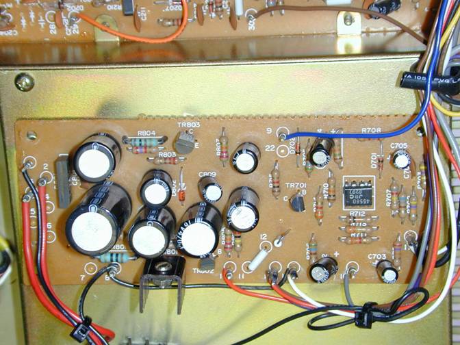
Figure 1: Original TM-1001 tuner power supply board before upgrade
Figure 2 below shows how your finished project will look (without the optional wiring for the audio output stage).
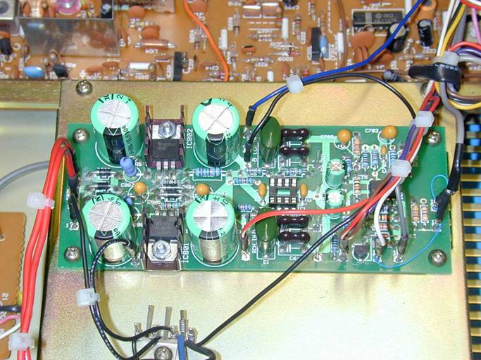 Figure 2: Finished TM-1001 tuner with
upgraded Power Supply Board project
Figure 2: Finished TM-1001 tuner with
upgraded Power Supply Board project
(Note this shows the optional components populated)
Assembling the TM-1001 Power Supply board printed
circuit assembly.
Have a printed copy of these instructions with you prior
to performing this assembly procedure.
Skills required:
While assembly of this circuit board is not a difficult procedure, the assembler should be familiar and comfortable with working on electronic equipment and using a soldering station and associated tools. Ensure good control of soldering iron temperature, not exceeding 600 degrees F, so the Power Supply Board is not ruined by excessive heat. If you are not familiar with working on electronic equipment or do not possess the proper equipment, it is recommended that you have this assembly performed by a service technician that can perform the Power Supply Board assembly and installation for you.
Tools required:
- Temperature controlled soldering station or iron – set to 600 degrees F
- 63/37 (preferred) or 60/40 rosin core solder - .031 diameter or smaller
- Good quality Needle nose pliers
- Good quality Diagonal wire cutters
- #2 Phillips screwdriver (not pictured)
- Axial lead former or bender
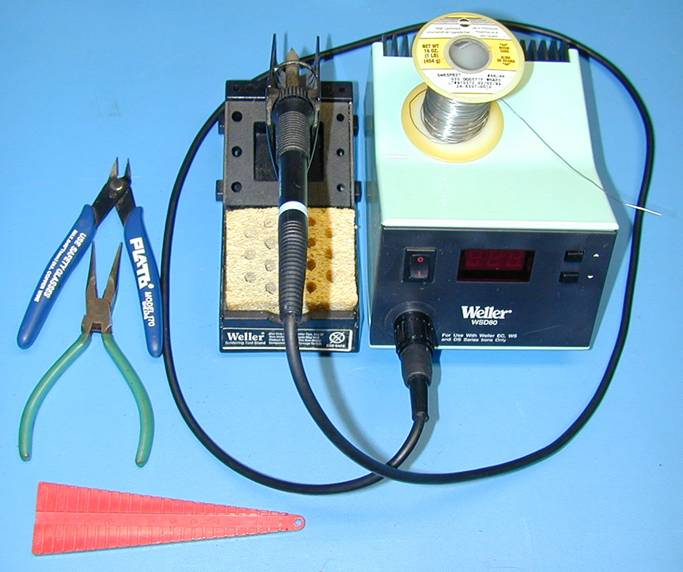
Figure 3: Tools Required
Optional Tools:
- A panavise with board holder is handy for assembling this project but is not required.
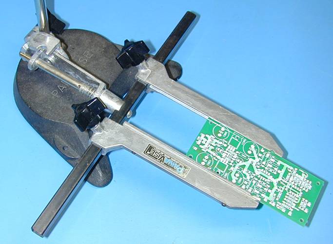
Figure 4: Optional Tools
Table 1
TM-1001 Upgrade Power Supply Board Parts List
|
Item |
Qty |
Mouser Electronics Part Number |
Description |
Ref. |
Mouser Price Ea. |
Ext. Price |
|
|
|
Integrated Circuits |
|
|
|
|
|
1 |
512-LM337T |
Voltage Regulator 1.5A, Negative, Adjustable, Linear |
IC802 |
$0.50 |
$0.50 |
|
|
2 |
1 |
511-LM317T |
Voltage Regulator, 1.5A, Positive, Adjustable, Linear |
IC801 |
$0.61 |
$0.61 |
|
3 |
1 |
595-RC4558P |
Amplifier - Operational High Performance, Dual |
IC701 |
$0.42 |
$0.42 |
|
4 |
1 |
595-OPA2134PA |
(Optional) Amplifier, Operational, High performance, low
distortion, Audio, Dual, OPA2134 |
IC1 |
$2.36 |
$2.36 |
|
|
|
Resistors |
|
|
|
|
|
5 |
2 |
282-10-RC |
Resistor, 10 ohm, 5%, 2W Small Metal Oxide |
R801-802 |
$0.19 |
$0.38 |
|
6 |
2 |
271-124-RC |
Resistor, 124 ohm, 1%, 1/4W, 50 ppm, Metal Film, Xicon |
R803, 805 |
$0.09 |
$0.18 |
|
7 |
2 |
271-560-RC |
Resistor, 560 ohm, 1%, 1/4W, 50 ppm, Metal Film, Xicon |
R705-706 |
$0.09 |
$0.18 |
|
8 |
1 |
271-680-RC |
Resistor, 680 ohm, 1%, 1/4W, 50 ppm, Metal Film, Xicon |
R704 |
$0.09 |
$0.09 |
|
9 |
1 |
271-1K-RC |
Resistor, 1.00K ohm, 1%, 1/4W, 50 ppm, Metal Film, Xicon |
R715 |
$0.09 |
$0.09 |
|
10 |
2 |
273-1.15K-RC |
Resistor, 1.15K ohm, 1%, 1/2W, 50 ppm, Metal Film, Xicon |
R804, 806 |
$0.10 |
$0.20 |
|
11 |
1 |
271-2.7K-RC |
Resistor, 2.70K ohm, 1%, 1/4W, 50 ppm, Metal Film, Xicon |
R708 |
$0.09 |
$0.09 |
|
12 |
2 |
271-3.3K-RC |
Resistor, 3.30K ohm, 1%, 1/4W, 50 ppm, Metal Film, Xicon |
R711, 714 |
$0.09 |
$0.18 |
|
13 |
2 |
271-10K-RC |
Resistor, 10.0K ohm, 1%, 1/4W, 50 ppm, Metal Film, Xicon |
R710, 712 |
$0.09 |
$0.18 |
|
14 |
1 |
271-15K-RC |
Resistor, 15.0K ohm, 1%, 1/4W, 50 ppm, Metal Film, Xicon |
R709 |
$0.09 |
$0.09 |
|
15 |
2 |
271-24.3K-RC |
(Optional) Resistor, 24.3K ohm, 1%, 1/4W, 50 ppm, Metal Film, Xicon |
R5-6 |
$0.09 |
$0.18 |
|
16 |
1 |
271-27K-RC |
Resistor, 27.0K ohm, 1%, 1/4W, 50 ppm, Metal Film, Xicon |
R701 |
$0.09 |
$0.09 |
|
17 |
1 |
271-47K-RC |
Resistor, 47.0K ohm, 1%, 1/4W, 50 ppm, Metal Film, Xicon |
R702 |
$0.09 |
$0.09 |
|
18 |
4 |
271-52.3K-RC |
(Optional) Resistor, 52.3K ohm, 1%, 1/4W, 50 ppm, Metal Film, Xicon |
R1-4 |
$0.09 |
$0.36 |
|
19 |
1 |
271-330K-RC |
Resistor, 330K ohm, 1%, 1/4W, 50 ppm, Metal Film, Xicon |
R713 |
$0.09 |
$0.09 |
|
20 |
1 |
271-470K-RC |
Resistor, 470K ohm, 1%, 1/4W, 50 ppm, Metal Film, Xicon |
R703 |
$0.09 |
$0.09 |
|
21 |
1 |
271-820K-RC |
Resistor, 820K ohm, 1%, 1/4W, 50 ppm, Metal Film, Xicon |
R707 |
$0.09 |
$0.09 |
|
|
|
Capacitors |
|
|
|
|
|
22 |
2 |
5982-15-500V68 |
(Optional) Capacitor, 68 pF, 500V, 5%, Mica Radial Lead |
C5-6 |
$0.59 |
$1.18 |
|
23 |
2 |
5982-15-500V150 |
(Optional) Capacitor, 150 pF, 500V, 5%, Mica Radial Lead |
C3-4 |
$0.51 |
$1.02 |
|
24 |
2 |
581-SR211E103M |
Capacitor, 0.01 uF, 100V, 20%, Z5U, Radial Monolithic |
C701, 801 |
$0.18 |
$0.36 |
|
25 |
2 |
581-SR215E224M |
Capacitor, 0.22 uF, 50V, 20%, Z5U, Radial Monolithic |
C810, 813 |
$0.25 |
$0.50 |
|
26 |
2 |
140-PF2A224J |
(Optional) Capacitor, 0.22 uF, 100V, 5%, Radial Polyester
Film |
C1-2 |
$0.34 |
$0.68 |
|
27 |
2 |
140-HTRL25V10-RC |
Capacitor, 10 uF, 25V, 105C Hi-Temp Radial Electrolytic |
C703, 705 |
$0.07 |
$0.14 |
|
28 |
2 |
80-T350F226K016AT |
Dipped Radial Tantalum Capacitor 16volts 22uF 10% |
C806-807 |
$0.79 |
$1.58 |
|
29 |
2 |
140-HTRL50V22 |
Capacitor, 22 uF, 50V, 105C Hi-Temp Radial Electrolytic |
C702, 704 |
$0.08 |
$0.16 |
|
30 |
2 |
140-HTRL50V1000-RC |
Capacitor, 1000 uF, 50V, 105C Hi-Temp Radial Electrolytic |
C803,805 |
$0.90 |
$1.80 |
|
31 |
2 |
140-HTRL25V2200-RC |
Capacitor, 2200 uF, 25V, 105C Hi-Temp Radial Electrolytic |
C808, 811 |
$0.75 |
$1.50 |
|
|
|
Discrete
Semiconductors |
|
|
|
|
|
32 |
1 |
512-2N3904BU |
Small Signal Transistors NPN Transistor General Purpose |
Q701 |
$0.05 |
$0.05 |
|
33 |
6 |
512-SB180 |
Rectifier, 1A, 80V PIV, Schottky Barrier |
D801-806 |
$0.19 |
$1.14 |
|
34 |
2 |
78-1N4148 |
Diode, High Speed Switching, 100V, 150mA |
D701-702 |
$0.03 |
$0.06 |
|
|
|
Miscellaneous |
|
|
|
|
|
35 |
2 |
532-577102B00 |
Heat-sink TO-220 Horiz/Vert Slim Channel Style |
IC801-802 |
$0.22 |
$0.44 |
|
36 |
1 |
649-DILB8P223TLF |
(Optional) DIP Sockets 8P IC SOCKET |
IC1 |
$0.12 |
$0.12 |
|
37 |
|
590-4140-400G |
(Optional) Prototyping Chemicals FLUX REMOVER - PLAST |
|
$12.46 |
$12.46 |
|
38 |
1 |
571-8-146276-0 |
Breakaway header strip, 0.318, 15u gold,
38 pin |
|
$3.60 |
$3.60 |
|
39 |
24 |
571-1-104480-6 |
Receptacle, 0.025” sq, crimp, 30u gold |
|
$0.13 |
$3.12 |
|
|
|
|
Mouser Total (req’d) |
|
|
$11.37 |
|
|
|
|
Mouser Total (including all optional
items on this parts list) |
|
|
$36.45 |
|
|
|
WOAD Supplied Kit Parts |
|
|
|
|
|
40 |
2 |
534-9401 |
Screw, 4-40 x 3/8”, Phillips
head |
IC801-802 |
$0.16 |
$0.32 |
|
41 |
2 |
534-9600 |
Hex nut, 4-40 |
IC801-802 |
$0.05 |
$0.10 |
|
42 |
2 |
|
Washer, flat, #4 |
IC801-802 |
|
|
|
43 |
2 |
|
Washer, internal tooth, #4 |
IC801-802 |
|
|
|
44 |
2 |
|
Heat Shrink Tubing 3/32” x 4” |
|
|
|
|
45 |
1 |
|
Wire, 30 AWG Kynar, 3” stripped
(supplied with PCB by White Oak Audio Design) |
W1 |
|
|
|
46 |
2 |
|
Wire, 2 x 24 AWG shielded
twisted pair, BLU/WHT, 13”, prepped, stripped and tinned |
|
|
|
|
47 |
1 |
WOAD TM-1001 PS PCB |
White Oak Audio Design Upgrade TM-1001
Power Supply blank PCB |
PCB1 |
|
|
|
48 |
REF |
WOAD TM-1001 PS Schematic |
Schematic, White Oak Audio
Design TM-1001 Power Supply Board |
SCH1 |
|
|
Order the parts above for the board assembly from Mouser Electronics. Pricing and/or part numbers of items above may have changed since the last revision of this document
Assemble from the silkscreen (component) side of the board (the silkscreen side of the board is the side shown in Figure 5). Start assembly with the smallest axial components and progressively add the larger components after completing the smaller components.
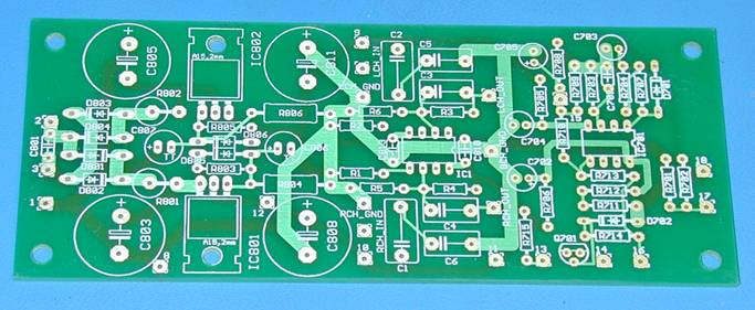
Figure 5: Blank Power Supply PCB
- Bend each 1/4W resistor to shape using the lead forming tool, use the 0.4” (10mm) hole to hole centers setting as shown in Figure 6 (bottom left).
- Bend each 1/2W resistor (R804, 806) to shape using the lead forming tool, use the 0.6” (15mm) hole to hole centers setting as shown in Figure 6 (middle left).
- Bend each 2W resistor (R801 - 802) to a U-shape by bending one lead over the body of the resistor as shown in Figure 6 (top left).
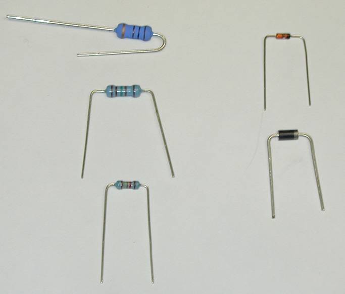
Figure 6, Lead Forming Illustration
- Use the parts list and silkscreen to locate each resistor value and location. Populate each resistor in the PCB according to the proper value/location. Splay the leads of each resistor slightly on the solder side of the board to keep the resistors retained in the PCB. Carefully flip over the PCB and solder each resistor lead to the board. Clip excess lead length, leaving about 1/16” extending beyond the solder fillet.
- Bend each small signal diode (D701-702) (Figure 6, top right) and each Schottky rectifier (D801-806) (Figure 6, bottom right) to shape using the lead forming tool, use the 0.4” (10mm) hole to hole centers setting as shown in Figure 3.
- Diode/rectifier polarity is
important. Since these are
polarized, it is VERY IMPORTANT that you orient these properly with
respect to the polarity shown on the silkscreen artwork. Failure to properly orient these diodes
may damage these components or your tuner.
Each diode/rectifier is marked with a polarity band around one end
of the component to show the cathode end of the component. Ensure that this band is oriented
correctly with respect to the band shown in the PCB silkscreen
- Use the parts list and silkscreen to locate each diode/rectifier component value and location. Populate each diode/rectifier in the PCB according to the proper value/location. Splay the leads of each diode/rectifier slightly on the solder side of the board to keep the diode retained in the PCB. Carefully flip over the PCB and solder each diode/rectifier lead to the board. Clip excess lead length, leaving about 1/16” extending beyond the solder fillet.
- Next insert ICs, IC701 and IC1 (Optional) into the board. Observe the polarity notch or dot at the pin 1 end of the IC and align it with the notch shown on the silkscreen (refer to Fig 11 on page 21 for a clear illustration of proper IC orientation). Since these are polarized, it is VERY IMPORTANT that you orient these properly with respect to the polarity shown on the silkscreen artwork. Failure to properly orient these ICs may damage these components or your tuner. If you desire, use the optional socket at location IC1 to allow you to try various types of amplifiers to suit your taste.
- Slightly splay pin 1 and pin 5 (diagonal corners) of each IC to retain them into the PCB. Carefully flip over the PCB and solder each IC lead to the board. Clip any excess lead length, leaving about 1/16” extending beyond the solder fillet.
- Next insert non-polar capacitors, since these are non-polar, it does not matter how you orient the part. Use the parts list and silkscreen to locate each capacitor value and location. Insert C801, C810 and C813 (Optional, C1 – C6) in the appropriate holes. Splay the leads of each capacitor slightly on the solder side of the board to keep the capacitors retained in the PCB. Carefully flip over the PCB and solder each capacitor lead to the board. Clip excess lead length, leaving about 1/16” extending beyond the solder fillet.
- Next insert the short polarized capacitors. Since these are polarized, it is VERY IMPORTANT that you orient these properly with respect to the polarity shown on the silkscreen artwork. Failure to properly orient these capacitors may damage these components or your tuner. Use the parts list and silkscreen to locate each capacitor value and location. Insert the short capacitors first: C702, C703, C704, C705, C806 and C807. Splay the leads of each capacitor slightly on the solder side of the board to keep the capacitors retained in the PCB. Carefully flip over the PCB and solder each capacitor lead to the board. Clip excess lead length, leaving about 1/16” extending beyond the solder fillet.
- Next insert Q701, the 2N3904 transistor. Since this device is polarized, it is VERY IMPORTANT that you orient it properly with respect to the polarity shown on the silkscreen artwork. Failure to properly orient this transistor may damage these components or your tuner. Splay the leads of the transistor slightly on the solder side of the board to keep the transistor retained in the PCB. Carefully flip over the PCB and solder each transistor lead to the board. Clip excess lead length, leaving about 1/16” extending beyond the solder fillet.
- Next insert the tall polarized capacitors. Since these are polarized, it is VERY IMPORTANT that you orient these properly with respect to the polarity shown on the silkscreen artwork. Failure to properly orient these capacitors may damage these components or your tuner. Use the parts list and silkscreen to locate each capacitor value and location. Insert the short capacitors first: C803, C805, C808 and C811. Splay the leads of each capacitor slightly on the solder side of the board to keep the capacitors retained in the PCB. Carefully flip over the PCB and solder each capacitor lead to the board. Clip excess lead length, leaving about 1/16” extending beyond the solder fillet.
- Next install the voltage regulator IC801. Bend the leads at 90 degrees to the case using the PCB thickness as a guide to ensure this bend occurs 1/16” away from the base metal tab of these regulators. Refer to Figure 2 to obtain a better understanding of this operation. The LM317 is installed in the IC801 location. Insert the 4-40x3/8” screw from the component side of the board with the threads sticking up. Drop the flat washer onto the top of the screw threads and then drop the heat-sink on top of this washer. The washer serves to separate the heat-sink from the board allowing better heat dissipation and to prevent long term discoloration of the PCB. Next drop the LM317 regulator with its leads formed into the PCB holes, orienting the hole in the tab on top of the screw that protrudes through the heat-sink. Drop the #4 internal tooth lock-washer on the screw and spin the 4-40 nut onto the screw to complete the assembly. Carefully tighten the screw with a #2 Phillips screwdriver, aligning all the parts as you tighten.
- Next install the voltage regulator IC802. Bend the leads at 90 degrees to the case using the PCB thickness as a guide to ensure this bend occurs 1/16” away from the base metal tab of these regulators. Refer to Figure 2 to obtain a better understanding of this operation. The LM337 is installed in the IC802 location. Insert the 4-40x3/8” screw from the component side of the board with the threads sticking up. Drop the flat washer onto the top of the screw threads and then drop the heat-sink on top of this washer. The washer serves to separate the heat-sink from the board allowing better heat dissipation and to prevent long term discoloration of the PCB. Next drop the LM337 regulator with its leads formed into the PCB holes, orienting the hole in the tab on top of the screw that protrudes through the heat-sink. Drop the #4 internal tooth lock-washer on the screw and spin the 4-40 nut onto the screw to complete the assembly. Carefully tighten the screw with a #2 Phillips screwdriver, aligning all the parts as you tighten.
- Carefully flip over the PCB and solder each of the regulator leads to the board. Clip excess lead length, leaving about 1/16” extending beyond the solder fillet.
- Now install the breakaway header strip contacts which will be used to terminate the tuner wires to your board. This makes for a very neat installation. Install one terminal pin in each wire termination hole. Breakaway header strips allow you to break off individual terminals by clipping at the notch in the black plastic located midway between each pin. Be careful as the pins tend to fly when you snip through the plastic. Use care. There are 24 locations including 4 on the tuner main PCB if you intend to wire in the optional Burr-Brown amplifier.
- For hole number 14 and 18, be sure to install the 30 AWG Kynar jumper wire into each hole before inserting the breakaway header pin.
- Start with hole number 18 and place one end of the 30 AWG Kynar wire that is supplied with the Power Supply board kit through the hole from the component side up to the point where the colored insulation ends. Carefully fold over the wire parallel to the top and bottom surface of the board to temporarily retain the wire. Then install the breakaway header pin in the same hole.
- Repeat the same operation for the hole number 14 with the other end of the Kynar wire. Dress the wire neatly as shown in the right hand side of Figure 2.
- Carefully clip any excess wire length, ensuring that you do not drop any of the clippings into the tuner circuitry.
- Carefully flip the board over and solder each breakaway pin on the solder side of the PCB.
- Inspect the finished board for solder shorts or splashes and for proper component orientation and polarity. Touch up as necessary.
- If you ordered the optional solder flux cleaner, clean the solder side of the board following the directions on the spray can. It is recommended you do this outdoors or in a place with proper ventilation.
- The board is now ready for assembly into your tuner.
Installing the TM-1001 Power Supply board printed
circuit assembly into the tuner.
Have a printed copy of these instructions with you prior
to performing this installation procedure.
Skill required:
While installation is not a difficult procedure, the installer should be familiar and comfortable with working on electronic equipment and using a soldering station and associated tools. Ensure good control of soldering iron temperature, not exceeding 600 degrees F, so the TM-1001 Power Supply Board is not ruined by excessive heat. If you are not familiar with working on electronic equipment or do not possess the proper equipment, it is recommended that you take your tuner to a service technician that can perform the Power Supply Board for you.
Tools required:
- Temperature controlled soldering station or iron – set to 600 degrees F
- 63/37 (preferred) or 60/40 rosin core solder - .031 diameter or smaller
- Needle nose pliers
- Diagonal wire cutters
- Wire stripper – 26 gauge
- #2 Philips screwdriver
Step by step installation procedure:
- Disconnect power and all connections from the TM-1001 tuner.
- Move the tuner to a suitable and clean work area.
- Using the Philips screwdriver carefully remove the 4 side cover screws and plastic bushings (2 on each side of the case) holding the wooden case to the tuner and the one screw in the rear, upper center of the back panel. Put the screws in a safe place for re-assembly later.
- Carefully remove the wooden case and put it out of the work area so that damage to the case will not occur.
- Locate the original Power Supply board assembly located on the left side of the tuner (while looking at the front face) just to the right of the power transformer.
- Mark each wire with a label tag prior
to disassembly. Each termination
point on the original power supply board has a number associated with it
ranging from 1 to 18. It is extremely
important that you do this correctly as many of the wires have the same
color code, making it difficult to complete the assembly if you have not
done this step properly. Mark each
wire tag with the number silkscreened on the board. The replacement board has numbers that
correspond exactly to the original although the locations on the new board
vary slightly from the original.
Double check to ensure you have the wires correctly numbered. (Note
that hole #13 has 3 wires attached to it (red, brown and purple))
- Either carefully unwrap each wire or use diagonal wire cutters to cut these wires right at the point that these wires begin to wrap around the posts.
- There are 4 self tapping screws that hold the original Power Supply to the metal chassis bracket that is part of the main tuner chassis. Using the #2 Phillips screwdriver, carefully unscrew the screws in the 4 corners of the Power Supply board. Put the screws in a safe place for re-assembly later.
- Carefully remove the original Power Supply board and put it to the side.
- Using your diagonal cutters, cut each of the wires to provide a clean end at a point approximately 1/16” of an inch where the wire insulation ends. Using your wire strippers, carefully strip about 3/16” (5 mm) of the wire insulation off each wire.
- Each termination location has one wire inserted through it EXCEPT holes number 13, 14 and 18. Special treatment is required for each of these locations as they each have 2 or more wires terminated to them.
- Hole number 13 has 3 wires to terminate to it, a red, brown and purple wire. Solder all 3 stripped wires into the receptacle valley as described above.
- Terminate each wire to the 0.025” square post mating receptacles (item 39), solder each wire to be terminated to a receptacle socket (item 39) using a small amount of solder in the valley just above the receptacle contact area. (Note Well: Be careful not to allow the solder to migrate down into the receptacle as it will ruin the mating area of the receptacle and you may not be able to install it on the breakaway header pin.) Using needle nose pliers, carefully form the crimp tabs around the insulation of each wire to provide strain relief.
- After you have terminated each wire in the step above, slip a 5/16” long sleeve of 3/32” heat shrink tubing over the junction of the receptacle termination and the wire insulation. This makes for a neater installation. Carefully heat shrink the tubing using a heat gun. Do not apply too much heat or you may damage the insulation.
- Carefully align the holes in the new Power Supply board with the metal bracket holes in the chassis in the orientation shown in Figure 2. Carefully re-install the screws removed in the prior step, leaving all screws loose until you have all 4 corners installed. Carefully tighten each. Do not over-tighten or you will crack the PC board or strip the screw holes.
- Start with hole #18 and work your way clockwise around the perimeter of the board. Carefully push each terminated wire receptacle onto its respective square breakaway header pin.
- Connect the white center conductor of the shielded wire labeled 17 to the board in the same manner as the prior step. There is only one wire for this pin.
- Connect the gray wire labeled 16 to the board in the same manner as the prior step.
- Next connect the white wire labeled #14 in the same manner as prior steps. This pin location also has 2 wires installed in it (the other end of the Kynar wire previously soldered in step above).
- Next connect the red, brown and purple wire grouping labeled #13. There are three wires at this location.
- Repeat for the red wire going to pin #10. There is only one wire at this location.
- Repeat for the black wire going to pin #8. There is only one wire at this location.
- Repeat for the black wire going to pin #1. There is only one wire at this location.
- Repeat for the red wire going to pin #3. There is only one wire at this location.
- Repeat for the red wire going to pin #2. There is only one wire at this location.
- Repeat for the blue wire going to pin #9. There is only one wire at this location.
- Your Power Supply board, once installed, will look like the illustration in figure 2. Dress the wires using tie-wraps as shown to neaten up the installation.
Installing the optional Burr-Brown
amplifier stage wiring to the main tuner board.
1. First step is to locate and remove the 4 electrolytic coupling capacitors from the existing circuit on the tuner main board to ready it for wiring in the new amplifier circuit on the TM-1001 Power Supply and Amplifier Board. These are C316, C317, C320 and C321 and are pictured in Figure 7.
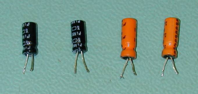
Figure 7, Existing capacitors C316, C317, C320, C321
2. These capacitors can be located just to the rear of the tuning flywheel and to the left of it while looking from the front of the tuner. Figure 8 shows the topside location of these 4 capacitors. The white silkscreen nomenclature will also indicate the accurate location of these 4 components.
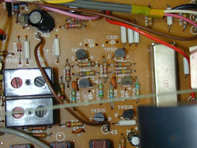
Figure 8, Topside location of C316, C317, C320 and C321
3. The locations of these 4 capacitors from the underside of the board vantage are pictured in Figure 9. Carefully unsolder them and use solder-wick or a solder sucker to clear the holes to allow for the next installation steps. Be very careful not to damage the main board while performing this operation.
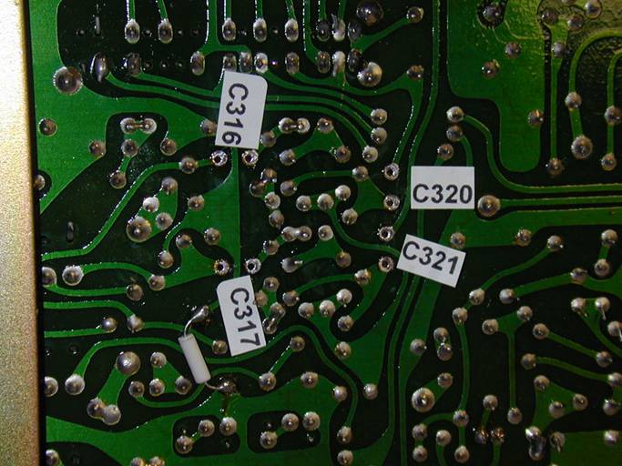
Figure 9, Capacitor locations on underside of main board
- Now install the breakaway header strip contacts which will be used to terminate the wire harness connectors to your board. Using these headers makes for a very neat installation. Install one terminal pin in each hole that you cleared out from the topside of the main tuner board. Breakaway header strips allow you to break off individual terminals by clipping at the notch in the black plastic located midway between each pin. Be careful as the pins tend to fly when you snip through the plastic. Use care. There are 4 locations on the tuner main PCB to wire in the optional Burr-Brown amplifier. These are the minus (-) polarity side of each of the 4 capacitor locations (the silkscreen denotes the positive (+) side of each capacitor, the minus (-) side is the one opposite this positive terminal). Carefully solder these contact pins into place.
- Now you are ready to make the connections between the tuner main board and the TM-1001 Power Supply and Amplifier board. The kit you received was shipped with a shielded twisted pair harness that has been prepped and ready to terminate with the connector receptacles. Terminate each wire of this harness to the 0.025” square post mating receptacles (item 39), carefully solder each wire to be terminated to a receptacle socket (item 39) using a small amount of solder in the valley just above the receptacle contact area. (Note Well: Be careful not to allow the solder to migrate down into the receptacle as it will ruin the mating area of the receptacle and you may not be able to install it on the breakaway header pin.) Using needle nose pliers, carefully form the crimp tabs around the insulation of each wire to provide strain relief.
- After you have terminated each wire in the step above, slip a 5/16” long sleeve of 3/32” heat shrink tubing over the junction of the receptacle termination and the wire insulation. This makes for a neater installation. Carefully heat shrink the tubing using a heat gun. Do not apply too much heat or you may damage the insulation.
- Referring to Figures 10, 11 and 12, attach each wire by sliding the receptacle socket onto each corresponding 0.025 square pin.
Connect the amplifier input wiring
- The white wire of the first twisted pair cable goes to C317 minus (-) on the tuner main board (Fig 10), the white wire at the other end of this same cable goes to the TM-1001 Power Supply and Amplifier pin labeled LCH_IN (Fig 11).
- The red wire of the first twisted pair cable goes to C316 minus (-) on the tuner main board (Fig 10), the white wire at the other end of this same cable goes to the TM-1001 Power Supply and Amplifier pin labeled RCH_IN (Fig 11).
- The ground wire of the first twisted pair cable goes to the TM-1001 Power Supply and Amplifier pin labeled RCH_GND (Fig 11).
Connect the amplifier input wiring
- The white wire of the second twisted pair cable goes to C321 minus (-) on the tuner main board (Fig 10), the white wire at the other end of this same cable goes to the TM-1001 Power Supply and Amplifier pin labeled LCH_OUT (Fig 11).
- The red wire of the second twisted pair cable goes to C320 minus (-) on the tuner main board (Fig 10), the white wire at the other end of this same cable goes to the TM-1001 Power Supply and Amplifier pin labeled RCH_OUT (Fig 11).
- The ground wire of the second twisted pair cable goes to the TM-1001 Power Supply and Amplifier pin labeled BCH_GND (Fig 11).
- The common ground wire from both twisted pair cable at the tuner main board end goes to the original equipment pin labeled 43 (Fig 10).
- If desired, dress the wires using tie-wraps to neaten up the installation.
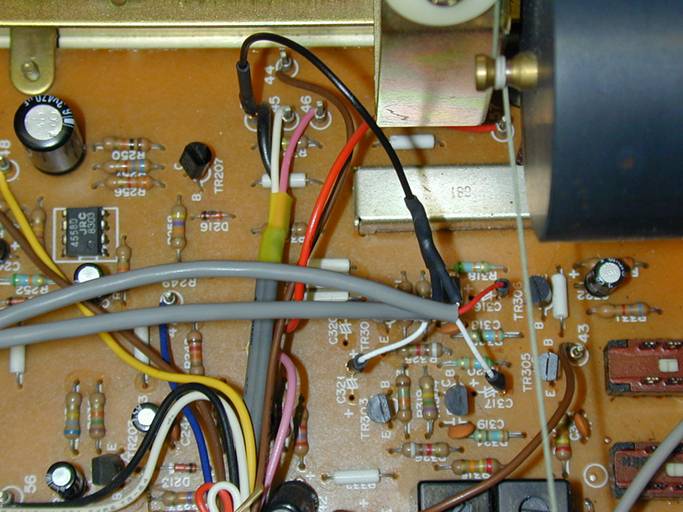
Figure 10, Harness terminations at the Tuner Main Board end
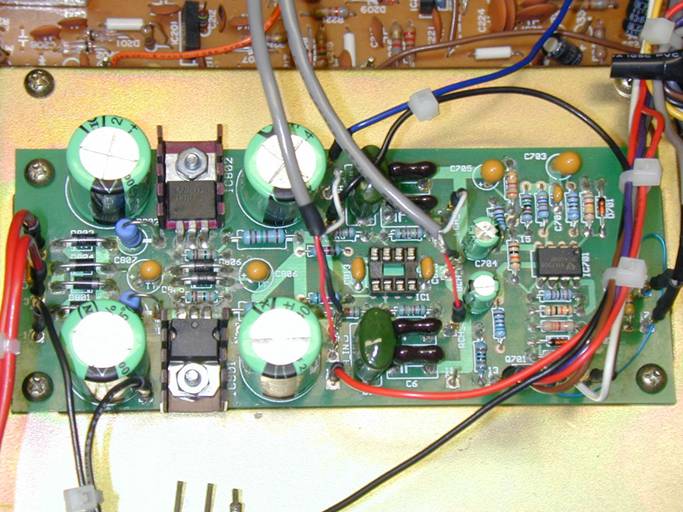
Figure 11, Harness terminations at the TM-1001 Power Supply and Amplifier Board end
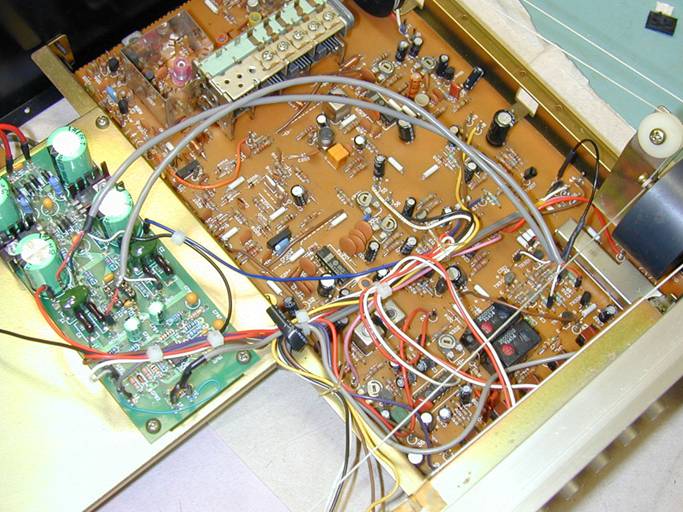
Figure 12, Wiring from Tuner Main Board to TM-1001 Power Supply and Amplifier Board
- Install the wood cover using the original hardware in
the reverse order of step 3 and 4.
Do not over-tighten the cover screws or you may strip the
self-tapping screws.
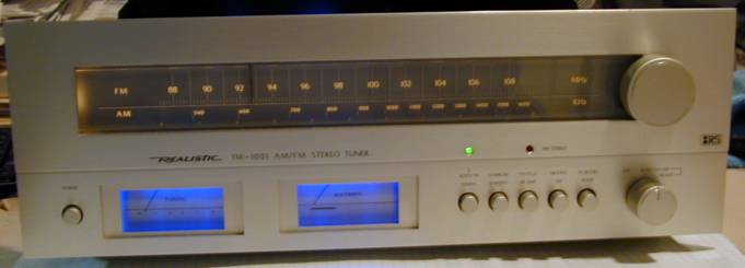
Figure 7
- Enjoy your tuner’s new upgrade TM-1001 Power Supply and Amplifier board. Tell your fellow vintage audio enthusiasts about White Oak Audio Design and our products.
|
Revision |
Revision Notes |
Revision Date |
Revised By |
|
A |
Original Release |
4/27/2008 |
JPK |
|
B |
Updated to include parts list for optional Burr-Brown audio output stage |
7/14/08 |
JPK |
|
C |
Updated to include pictures and instructions for installing optional Burr-Brown amplifier stage |
8/17/2008 |
JPK |
|
D |
Update to correct quantity errors in the 24.3K and 52.3K resistor values |
9/27/2008 |
JPK |
|
E |
Update to correct error for hole location 13. It has 3 wires terminated to it, not 2 as previously noted. |
10/5/2008 |
JPK |