Thank you for purchasing White Oak Audio Design’s TM-1001 Upgrade LED Light Board. White Oak Audio Design products are meticulously engineered and tested to ensure a direct drop in fit with your tuner.
The assembled and installed light board assembly will convert your TM-1001 tuner meter illumination to long life LEDs replacing the incandescent bulbs that burn out frequently and for which replacements are hard to find. In addition to longer life, the overall power consumption will be reduced as well as heat generated inside the enclosure. Your tuner will take on that nice blue look that Marantz was famous for.
Figure 1 below shows how your finished project will look.
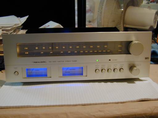
Figure 1 Finished TM-1001 tuner project
Assembling the light board printed circuit assembly.
Have a printed copy of these instructions with you prior
to performing this assembly procedure.
Skills required:
While assembly of this circuit board is not a difficult procedure, the assembler should be familiar and comfortable with working on electronic equipment and using a soldering station and associated tools. Ensure good control of soldering iron temperature, not exceeding 600 degrees F, so the LED Light Board is not ruined by excessive heat. If you are not familiar with working on electronic equipment or do not possess the proper equipment, it is recommended that you have this assembly performed by a service technician that can perform the LED Light Board assembly and installation for you.
Tools required:
- Temperature controlled soldering station or iron – set to 600 degrees F
- 63/37 (preferred) or 60/40 rosin core solder - .031 diameter or smaller
- Good quality Needle nose pliers
- Good quality Diagonal wire cutters
- Axial lead former or bender
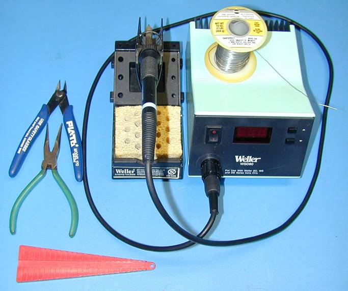
Figure 2: Tools Required
Optional Tools:
- A panavise with board holder is handy for assembling this project but is not required.
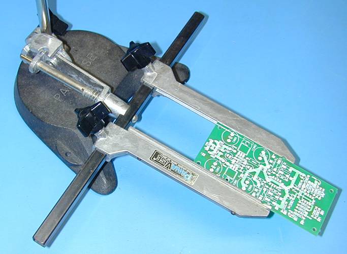
Figure 3: Optional Tools
Table 1
TM-1001 LED Board Parts List
|
Item |
Qty |
Mouser
Electronics Part Number |
Description |
Ref. |
Mouser
Price Ea. |
Ext.
Price |
|
1 |
2 |
140-XRL16V1500 |
Capacitor, Electrolytic 1500 uF, 20%, 16V, Xicon |
C1-2 |
$0.37 |
$0.74 |
|
2 |
6 |
604-WP7113PBC/H |
LED, X-Brite, Blue, Water Clear, T1-3/4, Kingbright |
D1-6 |
$1.97 |
$11.82 |
|
3 |
6 |
271-330-RC |
Resistor, 330 ohm, 1%, 1/4W, Metal Film, Xicon |
R1-6 |
$0.09 |
$0.54 |
|
4 |
1 |
583-RS101 |
Bridge Rectifier, 1A, 50V, Rectron |
B1 |
$0.43 |
$0.43 |
|
|
|
|
Mouser Total |
|
|
$13.53 |
|
5 |
1 |
WOAD LB PCB |
Blank PCB, White Oak Audio Design TM-1001 Light Board |
|
|
|
Order the parts above for the board assembly from Mouser Electronics. Pricing and/or part numbers of items above may have changed since the last revision of this document
Assemble the
silkscreen side of the board first (the silkscreen side of the board is the side
shown in Figure 4): 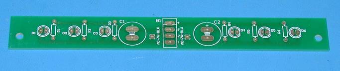
Figure 4 Blank Light PCB
- Bend the 6 LEDs to the proper shape as shown in Figure 5. Use the PC board thickness as a guide for where to bend the LED leads. The board is 1/16” thick. Using it, you will create a 90 degree bend in the lead wires 1/16” from the clear plastic base of the LED. IMPORTANT: LEDs are polarized. Each LED has a small flat adjacent one of the 2 leads. This signifies the cathode or negative side of the LED. The cathode lead length is also the shorter of the 2 leads coming out of the LED. Bend 3 LEDs in one direction and the remaining 3 in the opposite direction to match the imprints on the blank PCB. The board silkscreen is printed so that it shows this flat. Make sure you install the LEDs with the correct polarity or the light board will not work and you may damage the LEDs or your tuner. Also ensure that you install the LEDs so they point in the proper direction. The board is asymmetrical with respect to the mounting holes for the board. Look carefully at Figure 2 for proper orientation. All 6 LEDs should point away from the B1 (bridge rectifier) reference nomenclature on the silkscreen.
- Carefully solder each LED to the board as shown in the Figure 5. Space the plastic body of each LED approximately 1/16” off the face of the board. This will position the LEDs properly to shine into the top of each meter. Check the polarity of each LED before you solder it into place, aligning the flat on the LED plastic body with the imprint on the PC board silkscreen. After soldering, clip the excess lead length leaving about 1/16” protruding from the PC board surface.
- After you have soldered all 6 of the LEDs in, bend the leads of each of the six 330 ohm resistors on 0.4 inch (10mm) centers as shown in the photo. Carefully install each resistor into the locations marked R1 through R6 as shown in the photo, matching the imprint on the PC board silkscreen. Resistors are not polarized so it does not matter which way you orient them. Carefully solder each resistor to the board. After soldering, clip the excess lead length leaving about 1/16” protruding from the PC board surface. This side of the board should look like Figure 5 when this step is complete.
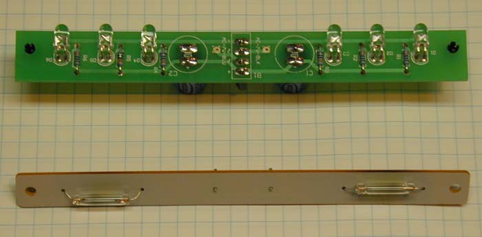
Figure 5 Silkscreen side assembly
- Refer to Figure 6 for the next steps. Flip the board over to the non silkscreened side as shown in the figure. The next 3 components will be installed from the backside of the board.
- Install bridge rectifier B1 into the 4 holes in the center of the board, observing the polarity of the bridge rectifier and the silkscreen legend. Make sure you install the bridge rectifier with the correct polarity or the light board will not work and you may damage the LED board components or your tuner. Wait to complete the next step before soldering.
- Install filter capacitors C1 and C2 into the two hole patterns to the right and left of the bridge rectifier observing the polarity of the capacitors and the silkscreen legend. Make sure you install these capacitors with the correct polarity or the light board will not work and you may damage the LED board components or your tuner.
- Carefully flip the light board assembly over and solder the leads of the bridge rectifier and capacitors. After soldering, clip the excess lead length leaving about 1/16” protruding from the PC board surface.
- Inspect the finished board for solder shorts or splashes and for proper component orientation and polarity. Touch up as necessary.
- The board is now ready for assembly into your tuner.
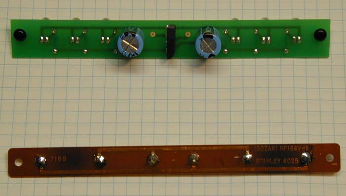
Figure 6 Bottom side assembly
Installing the light board assembly into the tuner.
Have a printed copy of these instructions with you prior
to performing this installation procedure.
Skill required:
While installation is not a difficult procedure, the installer should be familiar and comfortable with working on electronic equipment and using a soldering station and associated tools. Ensure good control of soldering iron temperature, not exceeding 600 degrees F, so the LED Light Board is not ruined by excessive heat. If you are not familiar with working on electronic equipment or do not possess the proper equipment, it is recommended that you take your tuner to a service technician that can perform the LED Light Board for you.
Tools required:
- Temperature controlled soldering station or iron – set to 600 degrees F
- 63/37 (preferred) or 60/40 rosin core solder - .031 diameter or smaller
- Needle nose pliers
- Diagonal wire cutters
- Wire stripper – 26 gauge
- #2 Philips screwdriver
Step by step installation procedure:
- Disconnect power and all connections from the TM-1001 tuner.
- Move the tuner to a suitable work area.
- Using the Philips screwdriver carefully remove the 4 side cover screws and plastic bushings (2 on each side of the case) holding the wooden case to the tuner and the one screw in the rear, upper center of the back panel.
- Carefully remove the wooden case and put it out of the work area so that damage to the case will not occur.
- Locate the original incandescent light board located on the left side of the tuner (while looking at the front face) directly above the 2 meters.
- Locate the 2 wires (one black and one blue wire) that are wire wrapped to 2 wire wrap pins located in the center and protruding from the original light board. Either carefully unwrap these wires or use diagonal wire cutters to cut these wires right at the point that these wires begin to wrap around the posts. Polarity does not matter so you don’t have to mark these wires.
- There are 2 small, black plastic rivets that hold the original light board to the metal brackets that are part of the tuner chassis. Carefully, using your fingernails, remove these rivets by pulling the center plastic plunger on each rivet out towards the rear of the tuner. Save these rivets as they will hold the new LED light board in place later on. Carefully remove the original light board and put it to the side.
- Using your diagonal cutters, cut the 2 wires to provide a clean end at a point approximately 1/16” of an inch where the wire insulation ends. Using your wire strippers, carefully strip about ¼” (6 mm) of the wire insulation off each wire.
- Using your soldering station, carefully insert and solder each wire into the pads provided on the LED Light Board with the wires entering the holes from the side of the board where the LED’s are mounted. Polarity does not really matter since this is an AC signal, however the board silkscreen denotes the Blue and Black insulation color references so you should follow this for consistency. Carefully clip any excess wire length, ensuring that you do not drop any of the clippings into the tuner circuitry.
- Carefully align the holes in the new LED Light board with the metal bracket holes in the chassis with the LED’s facing down toward the top of each meter and push one plastic rivet through the LED board and into the bracket. Once both rivets are installed, push the center plunger of each rivet in to secure the LED Light Board. Your light board, once installed, will look like the illustration in Figure 7 below. Make any minor adjustments to the LED orientation necessary to ensure that they point down correctly into the top of the meter lenses.
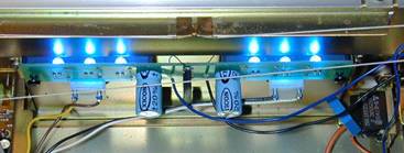
Figure 7 Installed Light Board Assembly
- Install the wood cover using the original hardware in
the reverse order of step 3 and 4.
Do not over-tighten the cover screws or you may strip the
self-tapping screws.
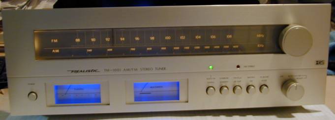
Figure 8
- Enjoy your tuner’s new long-life light board. Tell your fellow vintage audio enthusiasts about White Oak Audio Design and our products.
Revision Table
|
Revision |
Revision
Notes |
Revision
Date |
Revised
By |
|
A |
Original Release |
6/5/2007 |
JPK |
|
B |
Minor edits |
7/15/2007 |
JPK |
|
C |
Added photographic figures |
9/16/2007 |
JPK |
|
D |
Corrected part number for Bridge Rectifier from 583-R5101 to 583-RS101 |
4/23/2008 |
JPK |
|
E |
Corrected blue and black wire callout on page 5, instruction step #6. Added Tools Required and Optional Tools illustrations. Correct lead spacing on resistors to 0.4”. Added Revision Table. |
5/4/2008 |
JPK |